Background
For some investigative work that I had to do, I required an Availability Group (AG) that I could destroy and rebuild without impacting anybody else. Hyper-V was an obvious solution and this article describes the steps required.
Introduction
Hyper-V is Microsoft’s virtualisation software – enabling us to create virtual machines (VMs) that can then be used for a wide variety of purposes, without having to use additional hardware. In this article, I will be using these VMs to create a three-node AG on a Windows cluster.
As we will be using an Active Directory (AD) domain, we will need a Domain Controller (DC), as well as three servers for the three nodes of the AG. I’m creating three nodes for following articles, on how to upgrade an AG without downtime.
Requirements
For these examples, I will be using Hyper-V and installing Windows Server 2012 R2 and SQL Server 2012. Other versions of either can be used, as there are only minor differences in the setup and configuration – I’m using these versions to replicate the live configuration that I am working with.
Initially, create three VMs with Windows Server 2012 R2 – named AG-DC, AG-Node1, AG-Node2 and AG-Node3.
Each VM will be ‘Generation 2’, 2048MB of startup memory (using dynamic memory) – more is better, if your machine can handle it but remember that we will be running three VMs together, Connection is ‘Default Switch’, 512Gb Virtual Disk. We’re installing ‘Datacenter version (Server with a GUI)’, in order to include all functionality that we require.
This article will cover the following areas:
The article will cover the configuration of:
- Domain Controller
- Domain User Accounts
- Joining machines to the domain
- Windows Failover Cluster
- SQL Server Installation
- Configuration of an AlwaysOn High Availability Group
- Network and firewall settings required.
For ease of use, the password used throughout this demonstration is ‘Passw0rd1’.
Creating the Domain Controller (DC)
Having installed the operating system onto the VM ‘AG-DC’, we now need to configure the DC.
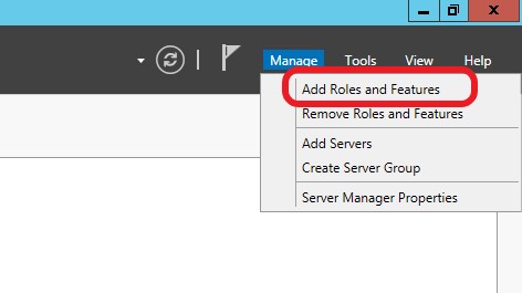
From the Server Manager dashboard, go to ‘Manage’/’Add Roles and Features’
Figure 1: Starting the Wizard
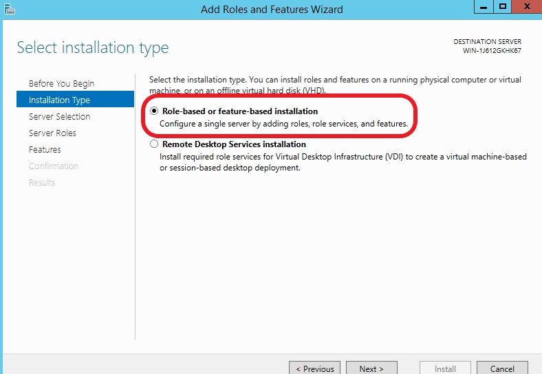
This will launch the ‘Add Roles and Features’ wizard, from which we need to select ‘Role-based or feature-based installation’ and press ‘Next’.
Figure 2: Selecting the type of Installation
The next screen is used to select the server to install the features. In this case there should be one server, so you can click ‘Next’.
Figure 3: Selecting the Server
The next screen is where the roles are selected. Click on ‘Active Directory Domain Services’. Another dialog screen might appear, confirming that the features for Active Directory Domain Services are required. If this should appear, ensure that the checkbox ‘Include management tools (if applicable)’ is selected. Click on ‘Add Features’ (if it appears) and ‘Next’.
Figure 4: Selecting Roles and Tools
The next dialog screen is for selecting the features. Select ‘.NET Framework 3.5 features’ and click ‘Next’.
Figure 5: Selecting features
The following dialog screen (entitled ‘Active Directory Domain Services’) gives details of additional action, which we don’t require for our purposes. Click ‘Next’, to get to the summary dialog.
On this screen, there might be a warning, which reads “Do you need to specify an alternative source path?”.
Figure 6: Confirmation Dialog
If this message appears, then click on ‘Specify an alternative source path’, where we can specify the path to a folder on the installation disk. In this demonstration, the image is mounted on the ‘D:’ drive.
In the ‘Path’ field, enter ‘D:\sources\sxs’ and click on ‘OK’.
Figure 7: Specify path for additional features
Now click on the ‘Install’ button and the installation will proceed. This may take several minutes.
Once completed, click on the ‘Close’ button, to return to the Server Manager.
On the Server Manager console, there is now a warning triangle on the top menu. Clicking on this will show a couple of messages, one of which has the option “Promote this server to a domain controller”.
Click on this, to launch a wizard for configuring the deployment.
Figure 8: Promoting to a Domain Controller
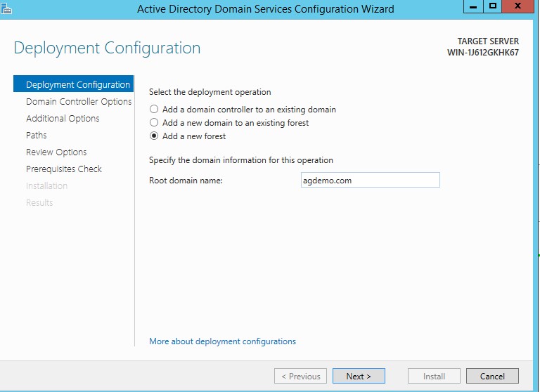
On the first screen of the wizard, we specify a new forest. Name this ‘agdemo.com’ and click ‘Next’.
Figure 9: Naming the new forest
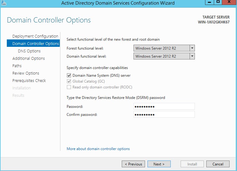
On the following dialog screen, ensure that it is set with the options shown below. The password used in this setup is ‘Passw0rd1’.
Figure 10: DC Options
The next dialog (DNS Options) displays a warning “A delegation for this DNS server cannot be created because the authoritative parent zone cannot be found”. For our purposes, we can ignore this message and click ‘Next’.
The next dialog (Additional Options) is to verify the NetBIOS name. This one field should be prepopulated with the name taken from the forest name. Check that is correct and click ‘Next’.
Figure 11: The NetBIOS domain name
The next dialog (Paths) specifies the folder locations for various aspects of the AD configuration. Leave these as the defaults and click ‘Next’.
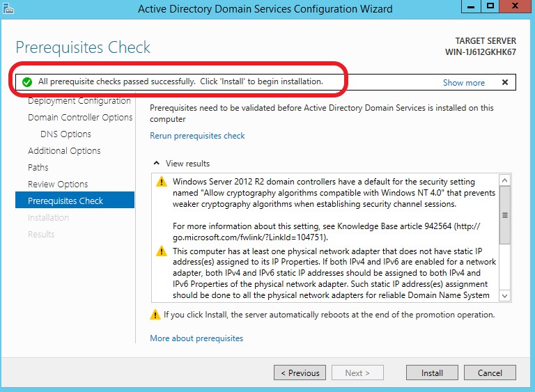
The ‘Review Options’ dialog summarises the settings that have been entered in the previous steps. Click ‘Next’ to go to the ‘Prerequisites Check’ dialog. It may process for a few seconds before showing the results.
Warning may be produced but as long as a green tick is displayed at the top of the screen, the installation can proceed.
Figure 12: Prerequisites Check completed
Click ‘Install’. This can take several minutes to complete.
Once installation has completed, the server will sign out the current session and restart. Once restarted, log back into the virtual machine as Administrator to move to the next step.
Setup Domain User Accounts
In order for AlwaysOn Availability Groups to function correctly, a domain user account is required that will have ‘CONNECT’ permissions on the ‘listener’. The default service account that SQL Server runs with after installation will not have these permissions so problems will arise when attempting to join each node to the Availability Group.
This section outlines the steps necessary to set up the new domain user account as well as a domain admin account.
If not already, log into the Domain Controller as Administrator and launch the Server Manager. Select “Active Directory Users and Computers” from the ‘Tools’ menu towards the top.
Figure 13: Creating the Users
Expand the ‘agdemo.com’ item on the left and select ‘Users’. This will bring up a list of all domain accounts towards the right.
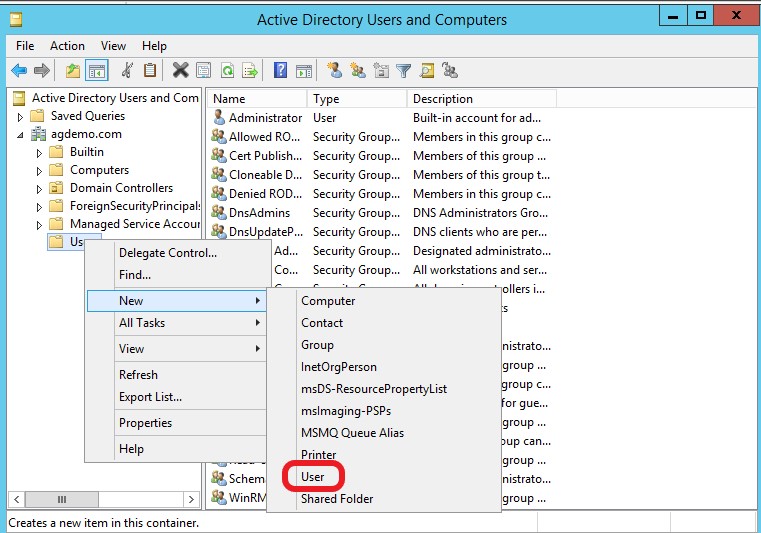
Right click ‘Users’ and select ‘New’ and then ‘User’.
Figure 14: Creating a User
To keep it simple, use ‘agadmin’ as values for ‘First name’, ‘Full name’ and ‘logon name’. Once done, click ‘Next’.
Figure 15: Setting the User properties
On the following dialog, set the password (‘Passw0rd1’) and ensure that the password does not require changing nor expires.
Figure 16: Password details
A confirmation dialog appears next, click ‘Finish’ to complete the creation of the user account.
Back in the list of users and computers, right-click on the newly created user and select ‘Properties’.
Figure 17: Updating the properties of the new user
Choose the ‘Member of’ tab and press ‘Add’.
Enter ‘Domain Admins’ and press Check Names then press OK.
Figure 18: Add user to groups
Press ‘Add’ again and repeat the previous step to add the user to ‘Administrators’.
Figure 19: Completed list of group memberships
Repeat the steps for creating the previous user, to create another user, called ‘SQLEngine’. This will only need to be added to ‘Administrators’.
Note: to repeat exactly, you may need to press the ‘back’ arrow on the ‘Active Directory Users and Computers’ dialog and then right-click ‘User’/’New User’, as the ‘properties’ menu option may not necessarily show this time.
Figure 20: Membership details for ‘SQLEngine’
Network Settings
As a final configuration step for the Domain Controller, a static IP address is required on the network connection.
Within Windows, search for and open “Network and Sharing Center” click on ‘Ethernet’ (step 1 in Figure 21), amend the network connection properties (step 2 in Figure 21). Highlight ‘Internet Protocol Version 4 (TCP/IPv4)’ (step 3 in Figure 21) and click Properties.
Figure 21: Network Settings
Change the settings to the following values:
IP Address: 192.168.0.50
Subnet Mask: 255.255.255.0
Default Gateway: <blank>
Preferred DNS Server: 127.0.0.1
Alternate DNS server: <blank>
Figure 22: Completed IP details
Configuration of the Domain Controller is now complete.
AG-Node1, AG-Node2 & AG-Node3 – Initial Configuration
This section describes the configuration steps necessary for the remaining virtual machines (AG-Node1, AG-Node2 and AG-Node3) before adding them to a new failover cluster. These steps are almost identical for each machine, with some minor differences.
Network Settings
Log in to each of the three machines as ‘Administrator’ (at this point, the only account that you can use).
Open the ‘Network and Sharing Center’ and amend the network connection properties for ‘Ethernet’. Highlight ‘Internet Protocol Version 4 (TCP/IPv4)’ and click Properties.
Select ‘Use the following IP address’ and configure the following settings:
| Setting | AG-Node1 | AG-Node2 | AG-Node3 |
| IP address | 192.168.0.51 | 192.168.0.52 | 192.168.0.53 |
| Subnet mask | 255.255.255.0 | 255.255.255.0 | 255.255.255.0 |
| Default gateway | 192.168.0.50 | 192.168.0.50 | 192.168.0.50 |
| Preferred DNS server | 192.168.0.50 | 192.168.0.50 | 192.168.0.50 |
| Alternate DNS server | <blank> | <blank> | <blank> |
Click on ‘OK’ and close the remaining dialogs, once completed.
Figure 23: Network Settings for AG-Node1
Joining to the AG Domain
Firstly, ensure that the VM ‘AG-DC’ is running.
For each of the servers ‘AG-Node1’, ‘AG-Node2’ and ‘AG-Node3’ the actions are the same, with a small difference to some of the values used.
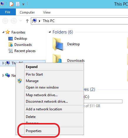
Open File Explorer, right-click on ‘This PC’ and select ‘Properties’.
Figure 24: Change the PC properties
In the ‘Computer name, domain, and workgroup settings’ section press ‘Change settings’. Press ‘Change…’ in the ‘Computer Name’ page.
Configure the following settings and Press OK, Close and Close again:
| Setting | AG-Node1 | AG-Node2 | AG-Node3 |
| Computer name | AG-Node1 | AG-Node2 | AG-Node3 |
| Domain | agdemo.com | agdemo.com | agdemo.com |
Figure 25: Joining a Domain
When you click ‘OK’ a login dialog will then appear. This is requesting the credentials for the domain account that was created on the AG-DC VM.
| Setting | Value |
| Username | agadmin |
| Password | Passw0rd1 |
Enter the username and password and click on ‘OK’. If the login is successful you will see a response ‘Welcome to the agdemo.com domain’.
On occasion, I have had an error returned from this, stating that the domain could not be contacted. This has succeeded after a couple of attempts, as long the IP addresses are correct, the domain name is correct and AG-DC is active. I can only assume it is the VM environments not reacting quickly enough.
Figure 26: Joined to the domain
Restart the VM.
Installing the Failover Clustering Feature
The Failover Clustering feature is required on each of AG-Node1, AG-Node2 and AG-Node3. The steps are identical for all machines.
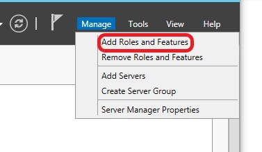
Log into the machines with the new ‘agadmin’ domain account (which was created on the AG-DC machine). Launch Server Manager and choose ‘Add Roles and Features’ from the ‘Manage’ menu at the top.
Figure 27: Add Roles and Features
In the ‘Installation Type’ tab, select ‘Role-based or feature-based installation’ and press Next.
Figure 28: Specifying installation type
In the following dialog the option ‘Select a server from the server pool’ should be selected. The current machine should be the only machine listed, so click ‘Next’.
Figure 29: Selecting the required server
The next screen is ‘Server Roles’. This requires no changes, so press ‘Next’ to proceed to the ‘Features’ tab.
Select ‘.NET Framework 3.5 Features’ and then select ‘Failover Clustering’. When Failover Clustering is selected, another dialog appears entitled ‘Add features that are required for Failover Clustering?’. Ensure the ‘Include management tools (if applicable)’ is checked and click on ‘Add Features’.
Figure 30: Adding Clustering Features
You are returned back to the ‘Features’ tab. Click on ‘Next’.
Figure 31: Final Selection of Features
On the next tab, there might be a warning at the top ‘Do you need to specify an alternate source path?…’
If this is the case, follow these simple steps to ensure an error-free installation:
- Click on the ‘Specify an alternate source path’ link at the bottom of the form.
- Insert the Winders Server installation DVD. (This will probably still be mounted by the VM).
- Assuming the Windows Server installation DVD mounts to drive letter ‘D:’, enter ‘D:\sources\sxs’ into the ‘Path’ box and press OK.
Figure 32: Specifying alternate source path
Having returned back to the ‘Confirmation’ tab, press ‘Install’ to launch the installation of the features.
Once completed, click on ‘Close’.
Figure 33: Completed Wizard
Firewall Settings
For testing purposes the simplest way around this is to simply disable the firewall on each node. However this section will outline the steps required to open these ports within Windows Firewall, so you can see how it is performed.
These steps are to be performed on all three servers – AG-Node1, AG-Node2 and AG-Node3.
Begin by launching ‘Windows Firewall with Advanced Security’ and clicking on the ‘Inbound Rules’ from the left pane. Click ‘New Rule…’ from the ‘Actions’ pane on the right side of the window.
Figure 34: Windows Firewall with Advanced Security
The ‘New Inbound Rule Wizard’ will appear, displaying the ‘Rule Type’ tab. Select the ‘Port’ radio button and press Next.
Figure 35: Selecting the Rule Type
On the following ‘Protocol and Ports’ tab, configure the following settings and press Next:
| Setting | Value |
| TCP or UDP? | TCP |
| All or specific local ports? | Specific: 1433,1434, 5022 |
Figure 36: Specifying the Protocol and Ports
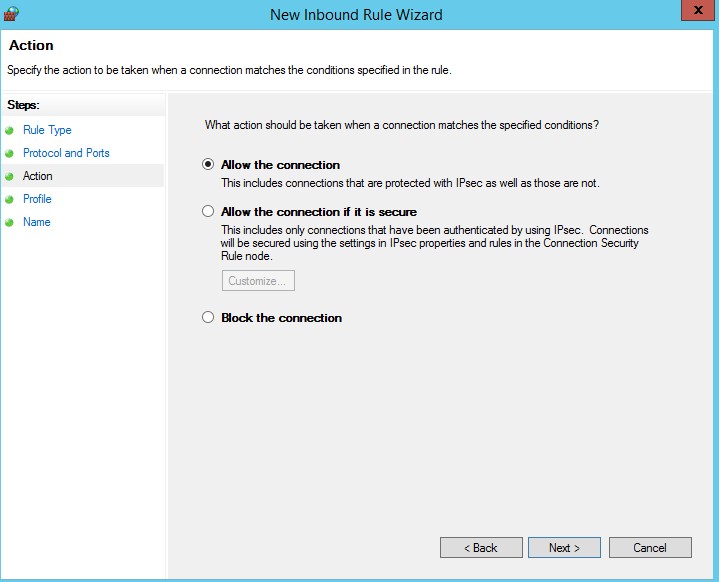
In the ‘Action’ tab, choose ‘Allow the connection’ and press Next:
Figure 37: The Action Tab
In the following ‘Profile’ tab, ensure all three check-boxes are selected.
Figure 38: Selecting the Profiles
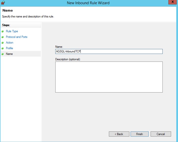
In the final tab, give the new Inbound Rule a name and press ‘Finish’ to complete the rule setup. For the purpose of this example the name ‘AGSQL-InboundTCP’ has been entered. The name doesn’t matter but it helps to make it something descriptive, for clarification.
Figure 39: Naming the Rule
There is another inbound rule and two outbound rules, all of which are created in the same manner. The details of all inbound and outbound rules are listed below. Create the additional rules to complete the firewall configuration:
New Inbound Rule 1 (already created in the steps above)
| Tab | Setting | Value |
| Rule Type | Type of rule | Port |
| Protocol and Ports | TCP or UDP? | TCP |
| All or specific local ports? | Specific: 1433,1434, 5022 | |
| Action | What action should be taken? | Allow the connection |
| Profile | When does this rule apply? | Domain, Private, Public |
| Name | Name | AGSQL-InboundTCP |
New Inbound Rule 2
| Tab | Setting | Value |
| Rule Type | Type of rule | Port |
| Protocol and Ports | TCP or UDP? | UDP |
| All or specific local ports? | Specific: 1433,1434, 5022 | |
| Action | What action should be taken? | Allow the connection |
| Profile | When does this rule apply? | Domain, Private, Public |
| Name | Name | AGSQL-InboundUDP |
New Outbound Rule 1
| Tab | Setting | Value |
| Rule Type | Type of rule | Port |
| Protocol and Ports | TCP or UDP? | TCP |
| All or specific local ports? | Specific: 1433,1434, 5022 | |
| Action | What action should be taken? | Allow the connection |
| Profile | When does this rule apply? | Domain, Private, Public |
| Name | Name | AGSQL-OutboundTCP |
New Outbound Rule 2
| Tab | Setting | Value |
| Rule Type | Type of rule | Port |
| Protocol and Ports | TCP or UDP? | UDP |
| All or specific local ports? | Specific: 1433,1434, 5022 | |
| Action | What action should be taken? | Allow the connection |
| Profile | When does this rule apply? | Domain, Private, Public |
| Name | Name | AGSQL-OutboundUDP |
Configure the Failover Cluster
Ensure that all four VMs are running (AG-DC and the three ‘Node’ VMs). Log onto AG-Node1 using the ‘agadmin’ domain account and launch ‘Failover Cluster Manager’ from the ‘Tools’ menu at the top of Server Manager.
Figure 40: Selecting the Failover Cluster Manager
Click ‘Validate Configuration’ from the ‘Actions’ pane at the right of the window to launch the ‘Validate a Configuration Wizard’.
Figure 41: Selecting Validate Configuration
At the next tab (‘Before You Begin’), click ‘Next’, to go to the ‘Select Servers or a Cluster’ tab.
Figure 42: Selecting Server or a Cluster tab
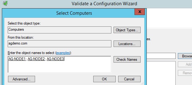
Clicking ‘Browse…’ from this page will display the ‘Select Computers’ dialog box. Enter ‘AG’ and press ‘Check Names’. A dialog box will display stating that multiple machines were found – highlight all three (AG-NODE1, AG-NODE2, AG-NODE3) and press OK.
Figure 43: Selecting the computers
Click ‘OK’ to return to the selection screen.
Figure 44: Selected Computers
Click ‘OK’ again and the computer will be displayed, along with their domain names.
Figure 45: Final selection with domain names
Click ‘Next’ to proceed to the ‘Testing Options’ tab. Select ‘Run all tests (recommended) and click ‘Next’.
Figure 46: Testing Options
On the Confirmation tab, click ‘Next’ to start the validation.
The tests then start, which may take several minutes.
Once the tests are completed the ‘Summary’ tab will be displayed with the results of the test. There may have been some error messages displayed, as the validation progressed. However, all being well a message will be displayed at the top of the form stating that testing was successful.
Figure 47: Validation Completed
Ensure that the ‘Create the cluster now using the validated nodes’ checkbox is ticked and press Finish. The ‘Create Cluster Wizard’ will display to begin the configuration of the Failover Cluster.
On the ‘Before You Begin’ tab, click ‘Next’.
The following tab (‘Access Point for Administering the Cluster’) needs a name for the cluster and an IP address.
The cluster name will be ‘AGCluster’ and the Address will be 192.168.0.100. Having entered those details, click ‘Next’.
Figure 48: Naming the Cluster
The confirmation screen will appear. Ensure the check-box for ‘Add all eligible storage to the cluster’ is checked and click ‘Next’.
Figure 49: Confirmation screen
The creation may run for a short while, and you will see the confirmation screen when completed.
Figure 50: Cluster Creation Completed
Click ‘Finish’ to return to the Failover Cluster Manager, which will now show the cluster details.
Figure 51: Failover Cluster Manager
SQL Server Installation
The next step is to install SQL Server 2012 R2 on AG-Node1, AG-Node2 and AG-Node3. The installation steps are identical for both machines. For my purposes I’m installign 2012 R2, but you can install any later version up to 2017, with the operating system of Server 2012.
Install SQL Server 2012 R2
Launch the SQL Server 2012 R2 installation wizard and choose ‘New SQL Server stand-alone installation’ at the top of the form.
Proceed through the tabs until you get to ‘Setup Role’. This should be ‘SQL Server Feature Installation’ and click ‘Next’.
Figure 52: Setup Role
On the Feature Selection tab I have selected the following:
Database Engine Services
SQL Server Replication
Reporting Services – Native
SQL Server Data Tools
Integration Services
Management Tools – Basic
Management Tools – Complete
SQL Client Connectivity SDK
Of these, only Database Engine Services, SQL Server Replication, SQL Server Data Tools and Management Tools (Basic and Complete) are required for the AG demonstration. I’m including the other features for future use in upcoming articles.
Click on ‘Next’ and progress through the ‘Installation Rules’ tab.
On the ‘Instance Configuration’ tab, ensure that ‘Default Instance’ is selected and click ‘Next’.
If the ‘Disk Space Requirements’ tab shows there is enough drive space, click ‘Next’.
On the ‘Server Configuration’ tab, we need to change some entries.
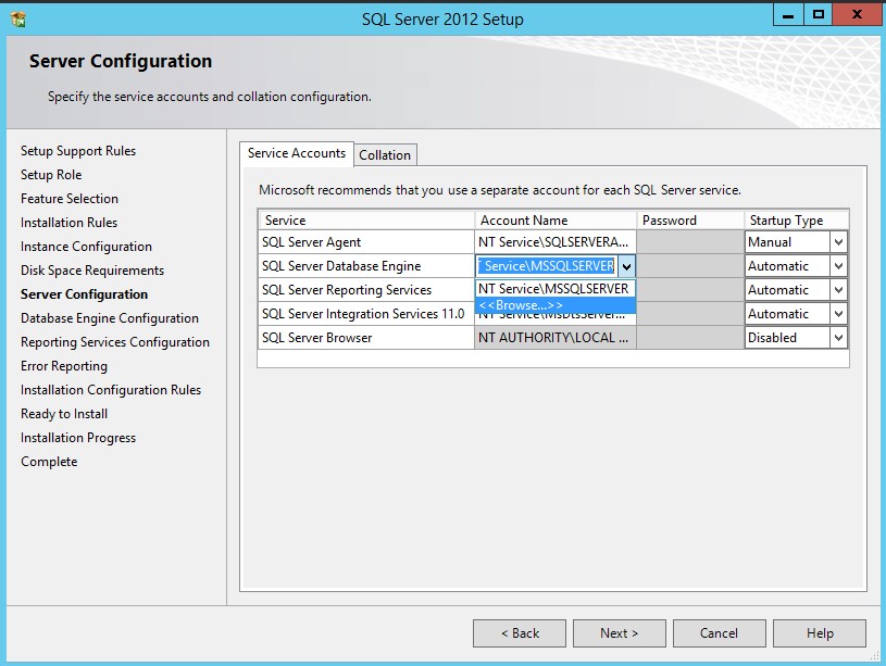
Click on the Account Name entry for ‘SQL Server Database Engine’ and click on ‘Browse’.
Figure 53: Setting the Database Engine Account
The ‘Select User, Computer, Service Account or Group’ dialog box will appear. Enter “SQLEngine” into the textbox and click “Check Names”. The full domain account will be displayed in the box. This is an account we created when creating the DC.
Figure 54: Entering the required Account
Figure 55: Click on ‘Check Names’
Click on ‘OK’ and then enter the password (‘Passw0rd1’). Click ‘Next’ when this is done.
Figure 56: Entering the Password for the SQLEngine Account
On the following tab (‘Database Engine Configuration’), select ‘Mixed Mode’ and enter a password of ‘Passw0rd1’. Mixed Mode is not required but I will be using this facility in future work – you can leave this as ‘Windows Authentication Mode’ if required.
Click on ‘Add Current User’ to add the ‘agadmin’ account as an administrator.
Figure 57: Adding Administration User
Click ‘Next’ on the following tabs, until you get to the ‘Ready to Install’ tab. Click on ‘Install’ to launch the installation.
Once completed, a summary of success will be displayed in the ‘Complete’ page. Click close to exit the installation wizard.
Figure 58: Successful Installation
Enable AlwaysOn High Availability
Log in to each of the servers as ‘agadmin’.
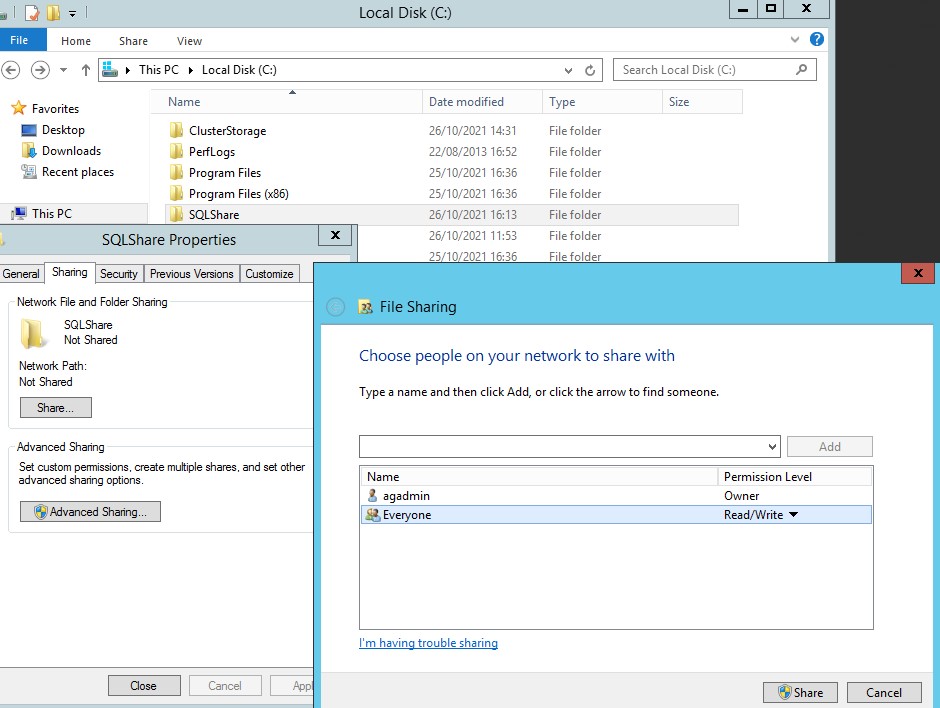
First of all, create a folder on the C: drive named ‘SQLShare’. Change the properties of this folder so that it can be read and written by everyone.
Figure 59: Creating the Shared Folder
Launch SQL Server configuration Manager and select “SQL Server Services” on the left pane. On the right pane right click on “SQL Server (MSSQLSERVER)” and choose ‘Properties’
Figure 60: Configuration Manager
On the ‘AlwaysOn High Availability’ tab, check the check-box for ‘Enable AlwaysOn Availability Groups’ and click ‘OK’.
Figure 61: Selecting AG Feature
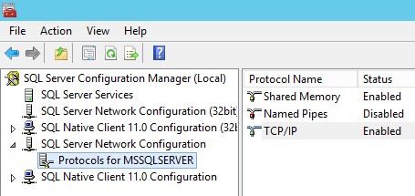
Expand ‘SQL Server Network Configuration’ and click on ‘Protocols for MSSQLSERVER’. In the right pane, if ‘TCP/IP’ is not already set to ‘Enabled’, right click on ‘TCP/IP’ and click ‘Enable’.
Figure 62: Enable TCP/IP
The SQL Server service needs to be restarted, in order to use any altered settings from Configuration Manager. Back in the ‘SQL Server Services’, right-click on ‘SQL Server (MSSQLSERVER)’ and select ‘Restart’. This will take a few seconds to restart the service.
Figure 63: Restarting SQL Server
Having enabled AG functionality on all three servers, connect to AG-Node1, as ‘agadmin’.
Now launch SQL Server Management Studio (SSMS).
Connect to AG-Node1 and create a new database. This database will be very simple – we’re just using this to prove the AG works.
Listing 1: Create New Database and one Table
CREATE DATABASE AGTest;
GO

USE AGTest;
GO

CREATE TABLE dbo.TestTable(
ID	INT IDENTITY(1,1) NOT NULL,
TestText	NVARCHAR(200) NOT NULL
);
GO

INSERT INTO dbo.TestTable(TestText)
VALUES ('Test One');
GO
Ensure the database is in Full Recovery and run a Full Backup. When a database is joined to an AG it must be in Full Recovery and have had a full backup completed against it.
Configuring the Availability Group
The final step is the configuration of the Availability Group.
Within SSMS, right click on ‘AlwaysOn High availability’ and select ‘New Availability Group Wizard’.
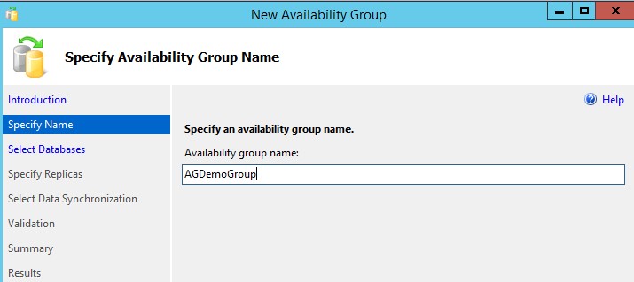
In the ‘Specify Name’ page enter ‘AGDemoGroup’ for the Availability Group name and click Next.
Figure 64: Specify AG Name
Click ‘Next’ to select the database required.
Select ‘AGTest’ and click ‘Next’.
Figure 65: Select Database
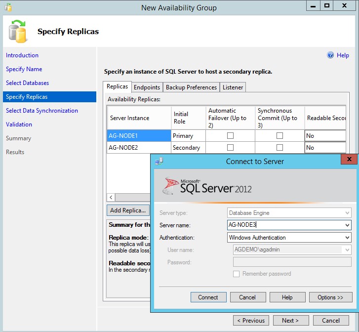
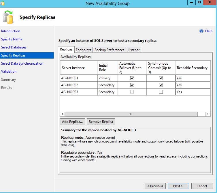
On the following tab (Specify Replicas) we add the servers that we want to add to the AG. Click on the ‘Add Replica’ button, specify the server name in the ‘Connect to Server’ field and click on ‘Connect’. Do this for the servers ‘AG-Node1’ and ‘AG-Node2’.
Figure 66: Selecting Servers
When all three servers are listed, select the check-boxes to enable synchronous commit and readable secondaries. Then click ‘Next’.
Figure 67: Selecting AG Behaviour
The next tab is to specify how the database is copied from AG-Node1 to the other servers. In this example we’ll have the wizard create the required backups, copy them to the ‘SQLShare’ folder and restore them on to the other servers.
Click on ‘Full’ for the synchronisation preference and Browse to the ‘SQLShare’ folder.
Figure 68: Synchronisation Method
Click ‘Next’ and the validation routine will run.
As long as there are no errors (warning are generally fine, for our purposes), you can click on ‘Next’.
When the wizard completes you will be presented with a ‘Results’ tab.
Figure 69: Completed Wizard
Within SSMS, go to ‘Always On Availability Groups’/’Availability Groups’, right-click on ‘AGDemoGroup’ and select ‘Show Dashboard’.
Figure 70: Selecting the AG Dashboard
This will show the three nodes of the AG and the database that is part of this AG, with a green tick against each entry, signifying a healthy replication status.
Note: When you close the VMs there might be an automatic failover triggered (because we specified such a behaviour in the setting), depending upon the sequence that the nodes close down. Don’t be surprised if you find that the Primary node has moved over when you next restart the VMs.
























5 thoughts on “Create an AG and Cluster with Hyper-V”